Friday, 23 December 2011

LAST CLASS OF 2011!!!!!!!!!!!!!!!!!

OH MY GOD!!!!!!!!!!!! Today was the last class of 2011. In fact I didn't realize about this when I came for the class in the morning. We had a totally different day in HPC. During the last two weeks we were getting trained in various subjects which are surely going to be useful in HPC.We went through the basics of discrete math, electronics, micro processors, digital electronics, computation and we had three assignments. To be very frank I had the most engaged two weeks. I was truly enjoying my days. I have the satisfaction of utilizing the semester break for something really useful. I had not been a technical person , in the sense that I will accept everything in its way. After attending the HPC classes, I have developed a quest for gaining  a technical reason for all I come across!!!. This change in me is giving a driving force.....

                                 Eventhough our group is known as HPC group nobody were aware about what actually was CHPC. It was today Sir gave us some basic idea about High Performance Computer. I was thrilled and surprised to know these facts. I cannot stop myself from appreciating Mahesh SIr for his splendid effort!!!! There were so many racks in which many cpu's were placed. These were the workstations. There were two maters which were totally different from the workstations. They divide the tasks among the workstation. Sir took us to the server room and explained about it not in detail because it is quite difficult. We use an Intel XEON processor for the super computer.

                                    The basic concept in CHPC is to parallising. Parallise means to divide the tasks in different nodes. parallising graetly depend on the dependancy.

                                                     x=y+z
                                                      c=x+2
 
cannot be paralllosed because the two equations  are dependent. K computers developed by fujistu, japan is the largest super computer in the world today. SIr showed us two videos about the facebbok data center and google data center. We could realise the difficulties encountered while designing a super computer. It is truly a commandable effort.

                                             Multi processor's and Multicores. Multi processor's have different processor's and in multi cores a single chip has many cores.

                                               We had an unexpected gift from Mahesh sir. A CHRISTMAS CAKE. We celebrated christmas in FISAT for the first time. Unni Kartha sir and Justin sir joined our celebrations.

                                              In the afternoon session we had some chit chats. Sir asked us to give feedback about the classes.  We all had just one comment to make that the classes were really worthy and we had so much of fun in FISAT. Sir gave us some works to be done in the holidays. That is a suspense. I'll be updating that in my blogs in the days to follow.


                                                                      HAPPY CHRISTMAS!!!!!!!!!!!!!

Thursday, 22 December 2011

DIGITAL ELECTRONICS IN APPLICATION...


Last day we had our first class on digital electronics and today Sir asked to design some logical circuits based on the facts that we have studied. Unlike the last time we were grouped into 2 with 4 members in each group. We were to solve 3 questions from among the 6 questions.

                             The questions selected by our group were

1. Design a full adder circuit.
2. Design a DFA to accept even number of zeroes.
3. Design a digital circuit to compare two 3 bit input.

   
                        Full adder circuit was the simplest question. We were to perform the add operation on 3 bit input. We implemented it using XOR and AND. The addition starts with the least significant bit  say z1 and z2 and the carry will be used as the third bit for the next two bits say y1 and y2. Thus it is continued.

                   Next was the comparator.  We consider two inputs A2 A1A0 and B2 B1 B0. To check if A and B were equal all the respective bits shall be equal. For A>B the cases can be:
A2=1 & B2=0
A2=1, B2=1.A1=1, B1=0
A2=1, B2=1, A1=1, B1=1, A0=1, B0=0
If the case is not any of these or A=B then it will be undoubtedly A<B

We implemented this circuit using four XNOR, one OR gate, two AND gates with three inputs, one AND gate with four inputs and one AND gate with two inputs.

                      Next was the circuit of a DFA to accept even number of zeroes. This was the most tiring circuit. We were not aware of the way by which we could give a sequential input and a random input too. Our circuit was found to be working for the ordered input 101010………

                  Even though we had a session on digital electronics as per the schedule of the day Miss didn’t turn up for some reasons and Mahesh Sir talked on some general topics. Sir was curious to know our parent’s opinion regarding the HPC classes.

Yes that was for the day. Had a good day at HPC as usual.

Wednesday, 21 December 2011

C..... MIND MAP.......DIGITAL ELECTRONICS


C Programming………….
                C language is the most powerful and efficient tool used by the programmers all around the globe. It can be considered as a very versatile language available now. The evolution of language is quite interesting. Like primitive men, who started to communicate with symbols people started using the most basic form called machine language to communicate with the system.  But it was quite tiring because the codes were completely written using 0’s and 1’s. Then came the assembly language which was developed to simplify human effort. But assembly language was not so user friendly and then came the era of high level language. It was the development of these HLL’s that made the tasks so easy for human beings. C language was developed for programming UNIX operating system(http://en.wikipedia.org/wiki/Unix) by  DENNIS RITCHIE at BELL LABORATORIES in the year 1969-1973. C is a general purpose language.
                C has got a well defined syntax. Every programmer shall take care of the syntax.  Once if there is any syntax error in the program then the compiler will detect those errors. Compiler is a program that converts the source code to the object code or machine level language.  Variables are used to represent memory locations, functions etc. They are identifiers and defined by the user according to his needs and requirements. When there is a statement like
                                                                X=10;
The compiler associates ‘X’ with the value 10. When a statement like
                                                                Z=X;
Is assigned then Z is directly associated with 10 and hence if the value of x is varied at any other part in the program the value of Z will not be varied. The Wikipedia page on C syntax is linked with.(http://en.wikipedia.org/wiki/C_syntax)
                                In machine level language there is no concept of data types. But in C language as every character in the character set is having an equivalent ASCII code there can be a contradiction between the numerical value ( say 97) and the ACSII code of characters( say the ASCII code of ‘a’ is 97). To avoid this difficulty data types were introduced.According to Wikipedia data type is"In computer programming, a data type is a classification identifying one of various types of data, such as floating-pointinteger, or Boolean, that determines the possible values for that type; the operations that can be done on values of that type; the meaning of the data; and the way values of that type can be stored"(http://en.wikipedia.org/wiki/Data_types). There are various data types in C like int,char,float,double . Each of these data types has their own memory requirement.
                               
                                Functions help to modularize the C code. There are various library functions available in various C header files. These functions are like black boxes and the real algorithm behind each of these functions are hidden from the user. I have learned C as a part of my curriculum but then I considered printf() to be a very easy to use function. And hence felt like disagreeing with Sir when he told that printf is the most complicated statement in C. But I realized that my assumptions were wrong when Sir asked to give the output of some printf statements.

                  I was really fascinated by a video of TED about the first artificial bird that fly like a real bird using ultraviolet rays. Markus Fischer led the team at Festo that developed this bird

                   Next up we had a very interesting session by Unni Sir. He helped us to prepare a mind map. It is very common that we have many random ideas in our mind when we think of a particular matter. Mind map is software that helps us to give a structure to our random thoughts. Here we tried to prepare the mind map for “AFTER B.Tech”. We had many ideas in our mind like MS, M.tech, PhD, a good job, other courses like MBA, joining defence and so on. Sir could give us a detailed explanation on the possibilities of each idea that we had.
  
                                Next we had a two hour session on digital electronics. I think it was a too short session because Parvathy miss had been so engaging and she took the classes so impressively. We started with the number systems decimal, binary, hexadecimal, octal. Each of these number systems has their own merits like decimal system is easy to count, binary system is used in machines, hex is having mare number of bits to represent data and so on. Then we went on with Boolean and arithmetic operations. In BOOLEAN ‘+’ is similar to an OR operation
                                                0+0=0
                                                0+1=1
                                                1+0=1
                                                1+1=1
And ‘.’ Is similar to AND operation
                                                0.0=0
                                                0.1=0
                                                1.0=0
                                                1.1=1

Functions could representd as sum of products and products of sums. To identify a function from the causal relation we can use a K- MAP or KARNAUGH MAP. In a K-map we group the bits so as to get the function. Each individual bit is called a literal. Sum of products is like group of AND gates connected by an OR gate and vice versa for POS.  A bubbled OR is a NAND gate and bubbled AND is a NOR gate.
SOP can be represented as NAND NAND gate and POS by a NOR NOR gate.  


Tuesday, 20 December 2011

A DAY IN MICROPROCESSOR LAB.........


  This was our second day in a lab. We had one day theory in microprocessor and toady we tried at applying what we have learned in writing programs. As the previous day we were grouped into 4 and each group had two members. We were to do two programs. The questions chosen by my group is given below.

1. Develop a program to convert decimal number to hexadecimal.
2. Find the square root of a number using successive approximation.

          We were able to execute the programs successfully.

ALGORITHM TO FIND SQUARE ROOT (SUCCESSIVE APPROXIMATION)

1. Set C as 01
2. Set E as 01
3. Set A as 09
4. Subtract A and C
5. Go to step 10 if A=0
6. Increment C by1
7. Increment C by 1
8. Increment E by 1
9. Repeat step 4-8
10. Copy the contents of E to A 
11. Store the value of A to a memory location
12. Stop


ALGORITHM TO CONVERT DECIMAL TO HEXADECIMAL (eg: 255)

1. Set A as 0
2. Set B as 02
3. Set C as 05
4. Set D as 05
5. Set E as 64
6. Go to 10  step if B=A
7. Sum contents of A and E
8. Decrement B by 1
9. Repeat steps 7-8 until B not equal to 0
10. Set the value of E as 0A
11. Go to step 15 if C=A
12. Sum the contents of E and A
13. Decrement C by 1
14. Repeat steps 12-13 until C not equal to 0
15. Sum the contents of D and A
16. Store the contents of A in a memory location
17. Stop

REVOLUTION!!!!!!!!!!!!!


During early period, people tried to express the natural occurrences in terms of the electrical parameters V and I. This was a very tedious process which motivated people to abstraction .The result of this abstraction are the laws of physics. OHMS law and MAXWELL’s laws are the most basic laws of physics. When these laws were abstracted we got the devices and components which led to the design of basic electronic circuits like the amplifier circuits. Basic electronics has two domains – ANALOG and DIGITAL. 555 IC, OP-amps etc belong to analog circuits. In digital electronics the devices have only two states of operation logic 0/logic1, on/off, true/false. Digital circuits are composed of logic gates like AND, OR, NOT, NAND, NOR, XOR, XNOR.

AND gate
AND GATE
NOR gate
OR GATE
                            
NOT gate
NOT GATE
http://www.kpsec.freeuk.com                                                              


In the higher versions of the digital circuits we attempted to control the speed of operation by using trigger or clock pulses. These are called clocked combinational logic. Moving bit more forward, digital circuits were designed to operate based on the instructions provided by a master and they are called instruction based clocked combinational logic. This is the basic idea behind a micro processor. The history of design of the first microprocessor is interesting. INTEL was the monopoly in the field of digital electronics then. BUSICOMM asked Intel to develop a programmable calculator. But the calculator developed by Intel had 12 units to perform the various tasks and was very large in size.  It was then a scientist TEDHOFF who put forth the idea to integrate all this circuits into a single unit. Thus the first microprocessor of its kind was developed and it was named as 4004 processor. Its function was to act as a programmable calculator. The second processor was 8008 and then many more followed.
.http://www.computerhistory.org/

                     A micro processor is a programmable clock driven register based electronic device which can receive binary digits as input, process binary data according to the instruction given by the master and gives an output in binary form. It is general purpose.

                    Registers are high speed memory cells which are located very close to the processor and hence the access time of such memory cells is very small. But registers are very costly and hence their availability in a system is very limited. There are two types of memory – Dynamic and Static. Usually devices like a capacitor when used they store charge but will discharge after a period of time. Hence these memory cells require constant refreshing and they are called dynamic memory cells. In static there is no need of refreshment. Registers are static memory cells.

                 An 8 bit micro processor kit was exhibited. Bit is the abbreviated form of binary digit. There was a micro processor and other peripheral chips, RAM, input unit, a display etc in the kit. When all this micro processor and other peripheral chips are integrated in a single chip we get a micro controller. Thus a micro controller is a device that is designed to perform a specific task.

PROGRAMMING MODEL OF 8085 PROCESSOR
The programming model of an 8085 processor is given below. Here the ALU unit is acting as the processor. It performs all the arithmetic and logical operations on the data. It is an 8 bit processor which shows that at a time the processor can perform the operations on 8 bit data. The registers available are program counter, instruction register, temporary register, B, C, D, E, H, and L. When more bit operation is to be performed then registers have to be paired. The pairing is done between BC, DE, and HL.  A PC holds the address of the next instruction to be executed and the IR holds the instruction that is currently getting executed. Group of wires are called BUS. There are three buses called address bus, data bus, and control bus. The bus can be bidirectional or unidirectional. Address bus is unidirectional as even if a read or write operation is to be performed by the processor the address will always be specified by the processor. Data bus is bidirectional and the control bus is unidirectional.       The width of the address bus in an 8085 processor is 16 bits and there can be 2^16 addressable locations. According to the definition available in Wikipedia interrupt is"In computing, an interrupt is an asynchronous signal indicating the need for attention or a synchronous event in software indicating the need for a change in execution ". There are two types of interrupts- vectored and nonvectored. In vectored interrupts the address to which the control to be transferred is pre defined and in the non vectored only processor is aware of the fact that it has to change the control but the location has to be provided by the user.
                        The flow of control in a 8085 processor is like as given below. After reset the address of the first instruction is to be placed in the program counter. This address is placed on the address bus and the processor fetches the instruction from the memory and it will be placed in the IR which will be decoded by the next stage instruction decoder and machine encoding cycle. To activate the required circuit inside the ALU proper trigger signal is to be generated which is done by the oscillator in the timing and control unit. There is a small micro processor and micro memory inside the timing and control unit which will activate the oscillator based on the input from the instruction decoder part. This trigger will activate the appropriate circuit in the processor.

                Addressing mode specify the way in which the data is accessed by the processor. Data can be accessed from the register or memory.
                  Next session we were taken to the micro processor lab. We wrote a code to perform the addition of two numbers, three numbers, n numbers and the output were verified using the 8 bit micro processor kit.
The code to perform addition of two numbers using assembly language code is given below.
LDA 5000
MOV B,A
LDA 5001
ADD B
STA 5000
HLT
Here LDA means to copy the contents in 5000 to the accumulator. Using mov command the value in accumulator is moved to a register B.  Then a second operand is accepted into the accumulator. ADD B command causes the contents in A and B to be added and result will be stored in A. STA command causes the result to be moved to an external memory. HLT command is used to end the operation.
The disadvantage of an assembly level language is that it is not user friendly and one has to be aware of the hardware to develop a high efficiency program.

Sunday, 18 December 2011

THEORY........TO......... PRACTICALS.....


Today was a totally different day when compared to the other days. We made an attempt to make a practical approach of what we have learned so far. Sir gave us 8 questions and asked us to solve two questions in groups with two in each group. Each group was to solve two different questions and there should be a question from octave and one from electronics .

                      The questions chosen by my group are given below,
1. Identify the brightest point in an image using octave.
2. Design and implement circuit that will turn on a DC motor in the presence of light source.

                   For finding the brightest point we thought of adding the RGB factor of each pixel and then compare with an initially assigned maximum value. If the sum obtained from a particular pixel is found to be greater than the maximum value then it will be substituted in the max variable. Executing this logic in two loops to navigate through row and column and a third loop to add the RGB factor of each pixel, the brightest point will be obtained. We could, to an extent implement the code and we tried it with two images.  


Next attempt was to design the electronic circuit


We used the circuit given above to make the motor run in the presence of light.
                    Light dependent resistor also called an LDR is a resistor whose resistance value depends on the light falling on it. When the light falls on the resistor its effective resistance decreases and vice versa. We need a high resistance value at the base for better performance of the motor. That was in fact the most challenging part about the circuit. The circuit was wired up properly but the LDR was not seen to get properly activated and hence the motor was not properly seen to be working. 

Saturday, 17 December 2011

AN ENCOUNTER WITH ELECTRONIC CIRCUITS.....


Busy schedule for the day started at 7.30.Sir for the first time took us out  of the central computing lab to the hardware lab. The lab is hpc group's workshop. There was everything needed for the experiments in electronics in the lab.

                            Sir started off with the basics. Active and passive components. Active components are those which do not require an external energy source whereas passive components are those which require sources to operate. Resistors are the most basic passive component. Resistors are specific in the way that they have color bands surrounding it. The value of a resistor can be obtained from the following table.


Capacitors are used for storing charges. For high power devices capacitors of larger size and capacitance value are used.

                      Diode is an active device that is used widely in circuits due to its ability to conduct current in unidirection. Diodes have two terminals and depending on the biasing applied to the terminals diode can be forward or reverse biased. Diodes is theoretically said to conduct in the forward biased condition. Light emitting diodes popularly known as LED was used in the circuit with a resistor and voltage power supply to demonstrate its operation.

                 Next up we designed a half wave rectifier that is used to covert an ac into a pulsating dc. DSO or digital storage oscilloscope was used to verify the waveforms. As per the information from Wikipedia -The digital storage oscilloscope, or DSO for short, is now the preferred type for most industrial applications, although simple analog CROs are still used by hobbyists. It replaces the unreliable storage method used in analog storage scopes with digital memory, which can store data as long as required without degradation. It also allows complex processing of the signal by high-speed digital signal processingcircuits.[“1] (http://en.wikipedia.org/wiki/Oscilloscope#Digital_oscilloscopes)


                                         en.wikipedia.org/wiki/Oscilloscope


                   Transformers are voltage varying devices. They can either step up or step down the voltage. A transformer is essential in DC power supplies as most of the devices work on small DC voltages. The output of the half wave rectifier shown below has ripples 
or AC components and to remove it capacitor filter is used 


http://www.google.co.in/imgres?imgurl=http://www.visionics.ee/curriculum/Experiments/HW%2520Rectifier/Images/Image227.gif&imgrefurl=http://www.vi


                       Transistor is an active device that is used for switching  and amplification. Transistor circuits were really challenging. When the voltage across the transistor is greater than .7V transistor will be closed and it will conduct current. For active mode of operation the emitter junction should be forward biased and the collector junction should be reverse biased. Even though transistors have three terminals a high power transistor is such that its body is acting as the collector. This is enabled to dissipate the heat and usually heat sinks are attached to these transistors. We made a motor run by using a transistor switch. When AC source is used to drive the motor we would expect the motor to vibrate between the ON/OFF state as the source signal is switching between positive and negative cycles. But due to the effect of inertia of rotation and the source being continuous this change over is not really felt.
  
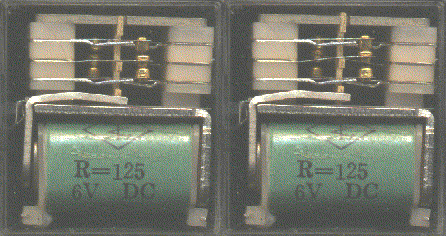
             Relays are electrically operated switch. Basically it uses the principle of electromagnetic induction. When voltage is applied across the input terminals the coil gets charged and gains the properties of a magnet. There is normally closed and normally open pair of output terminals in a relay. Relays was used to light a bulb . Coupling relays to the secondary of a transformer through a battery, we get a huge voltage at the primary.


                               Next discussion was on the most sought out component of the modern era. INTEGRATED CIRCUITS. IC’s changed the face of the world. Thousands of transistors are integrated on to a single chip made of semiconductor substrate. T his helped to reduce the size of mobile phones, computers etc. 78xx series of IC’s are used as voltage regulators. As most of the electronic devices work on 5v DC sources it is essential to reduce the available energy and it can be achieved by just placing 7805 IC.
                 
                                               http://en.wikipedia.org/wiki/Integrated_circuit


                  We put forwarded some ideas to  apply for the intel embedded challenge. Some of the ideas were really mind blowing. If these ideas are implemented in the expected way it can solve many problems.

                      
                                          Yes… that was for the day.